Home / Services / ESD design tools

ESD design tools

Circuit simulators are built for milliwatts. ESD happens at around ten watts, ten amps and nanoseconds. We extend your PDK so your designers can simulate ESD before tape-out.

What we do

We develop ESD electronic design automation: compact models, ESD-enabled design kits and verification engines that make ESD design predictable rather than a matter of ‘black magic’.

  • ESD compact models in Verilog-A, valid in the ESD regime and scalable with the main ESD layout parameters
  • Implementation in the standard Cadence design-kit environment, with ESD schematic views and Spectre and HSPICE simulation
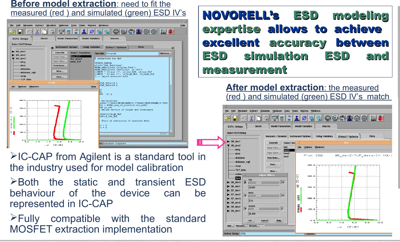
  • Model calibration to silicon TLP data, using IC-CAP
  • ESD PDK content: ESD component library, ESD layout DRC deck, parasitic ESD device extraction, integration rules based on ESD SOA, ESD library cells and full-chip integration rules
  • Verification engines: a static topology rule checker and a dynamic checker that calculates time-domain SOA for every IC component
  • Simulation of HBM, CDM and IEC stress waveforms and of TLP behavior

Who this is for

Foundries, library vendors and IC design houses that want ESD simulation and verification inside their standard design flow.
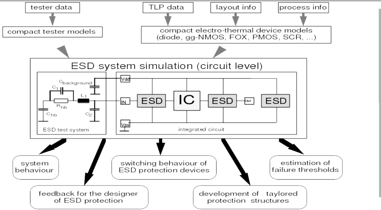
System-level ESD simulation diagram with tester models and compact electro-thermal device models
Our ESD simulation approach: compact tester models and electro-thermal device models in a circuit-level simulation of the ESD test system and the integrated circuit.

ESD-enabled design kits

Our ESD know-how supports the development of ESD-enabled PDKs in any technology, either as an extension of your standard PDK or on its own.
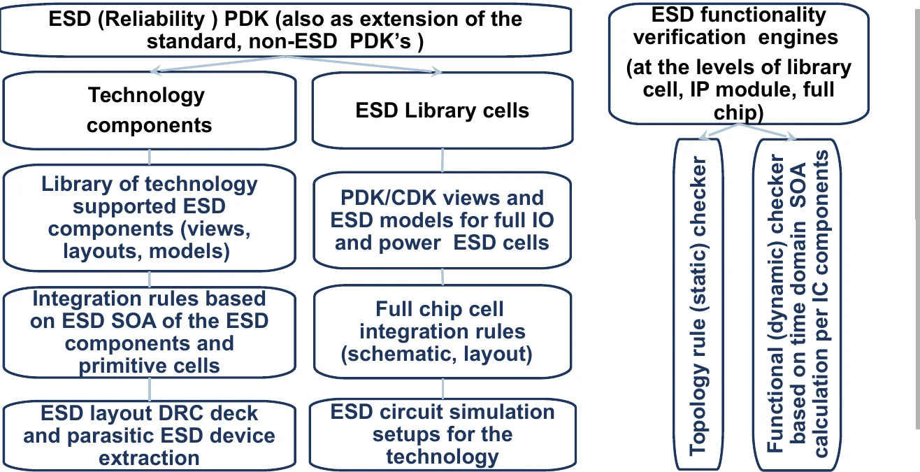
Structure of an ESD reliability PDK with technology components, library cells and verification engines
The structure of an ESD (reliability) PDK: technology components, ESD library cells, integration rules, simulation setups and verification engines.

Models that match the silicon

Snapback, avalanche and bipolar effects are captured in equivalent-circuit models that extend regular SPICE models into the ESD regime.
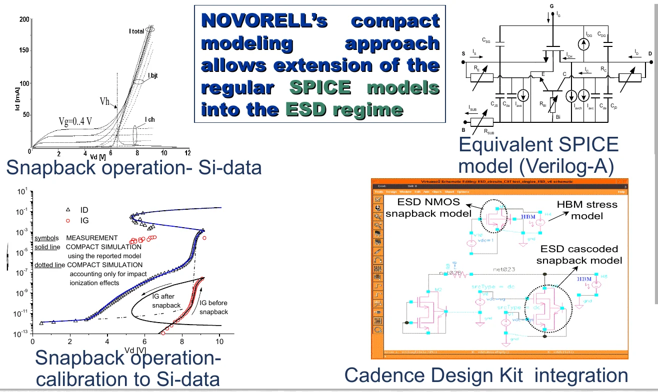
Snapback silicon data, equivalent SPICE model and Cadence design kit integration
Snapback operation: silicon data, the Verilog-A equivalent model, calibration to the data and integration in the Cadence design kit.
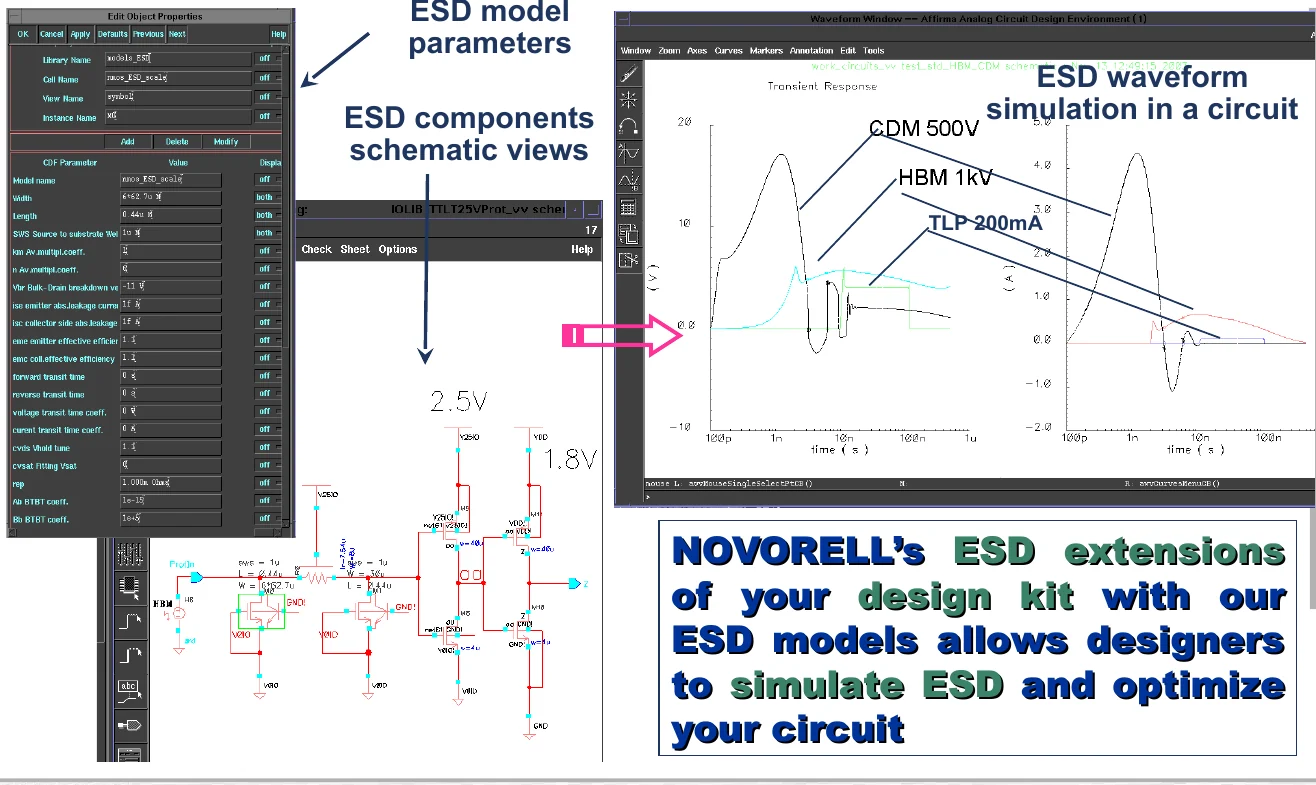
ESD model parameters, component schematic views and simulated ESD waveforms in a Cadence environment
ESD extensions of your design kit: ESD model parameters and schematic views in Cadence, and simulated CDM, HBM and TLP waveforms.
ESD model calibration in IC-CAP before and after parameter extraction
Model calibration in IC-CAP: measured (red) and simulated (green) ESD IV curves before and after parameter extraction.
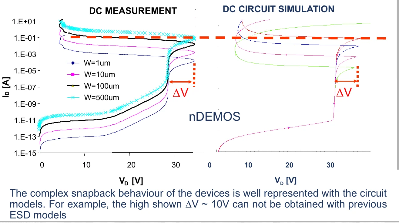
DC measurement and DC circuit simulation of nDEMOS snapback
Model validation for an nDEMOS device. The large snapback ΔV of about 10 V cannot be obtained with previous ESD models.

Tell us about your ESD challenge

Send a short description of your technology, product or failure and we will tell you how we would approach it.